

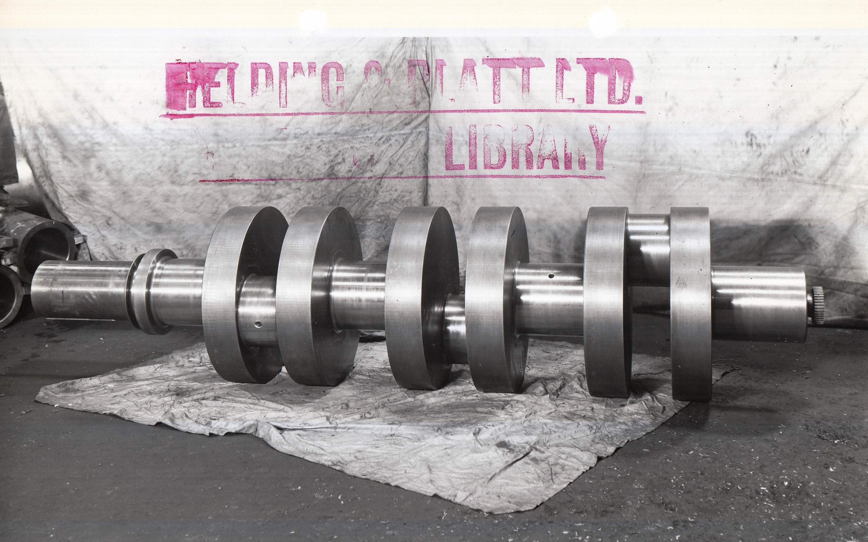
In the first photo note the gear wheel on the extreme right. This engaged with the mechanical lubricating pump attached to the outside of the pump.
On the same photo, extreme left, note the thin flange (machined as part of the crankshaft); this obviated the need to fit an oil-tight seal on the crankshaft as any oil leaking out of the bearing on this side of the crankshaft was caught by the flange and was ‘flung’ into the base of the bedplate.
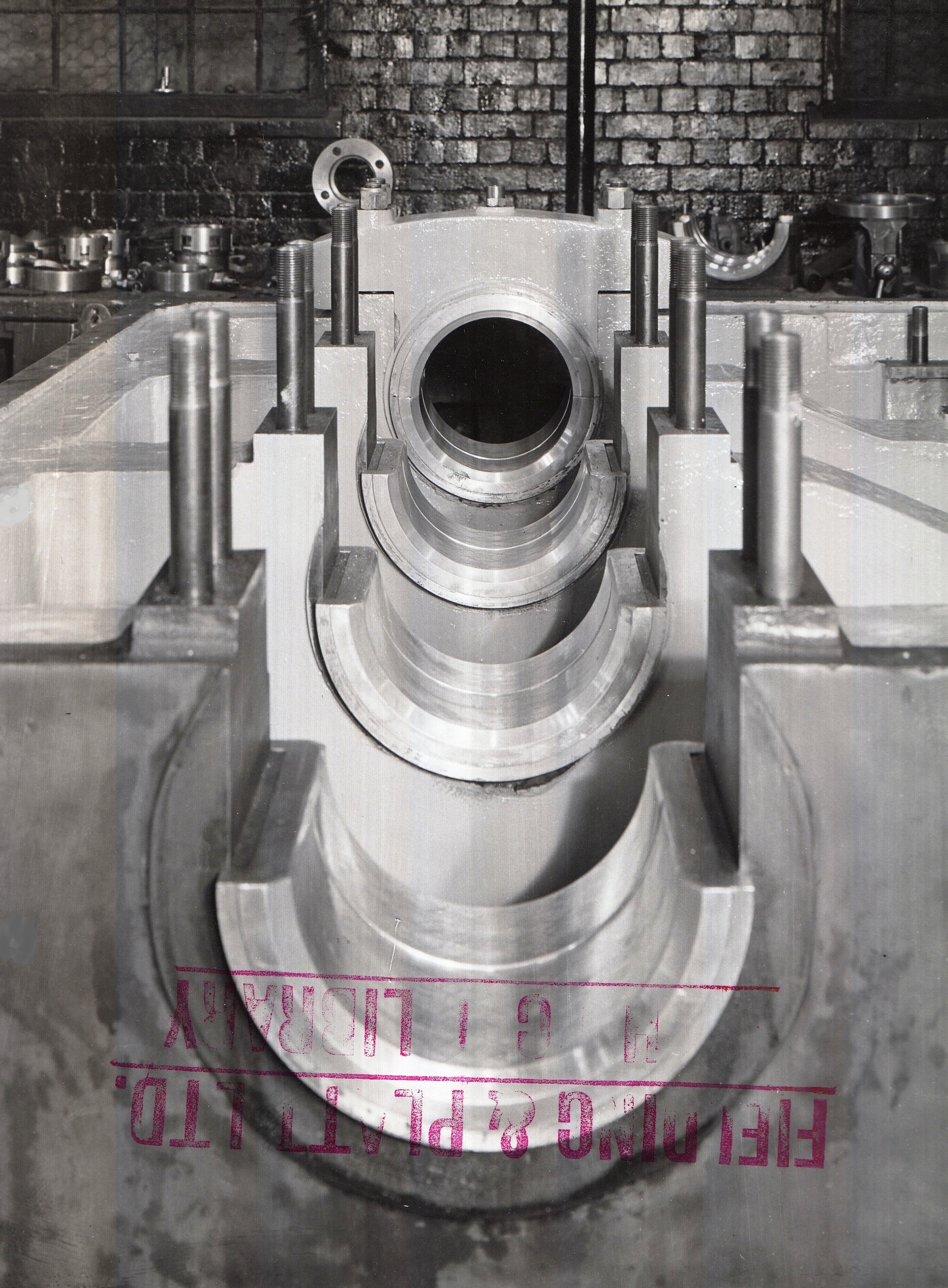
In the second photo, the bearing ‘shells’ were lined with white metal and the lower halves were ‘scraped-in’ to ensure a good and even bearing surface on the crankshaft. (This procedure applied to all sizes of pump fitted with white metal bearings and also included the connecting rod bearings).
Click on a photograph to enlarge an image.
Click on the hyperlink to see Notable Orders from the 1940s.
If you have any recollections about working on larger pumps please share your memories at the bottom of the page by clicking on the words Add a comment about this page.


No Comments
Add a comment about this page