


Click on a photograph to enlarge an image.
Click on the hyperlink to see other Notable Orders from the 1960s
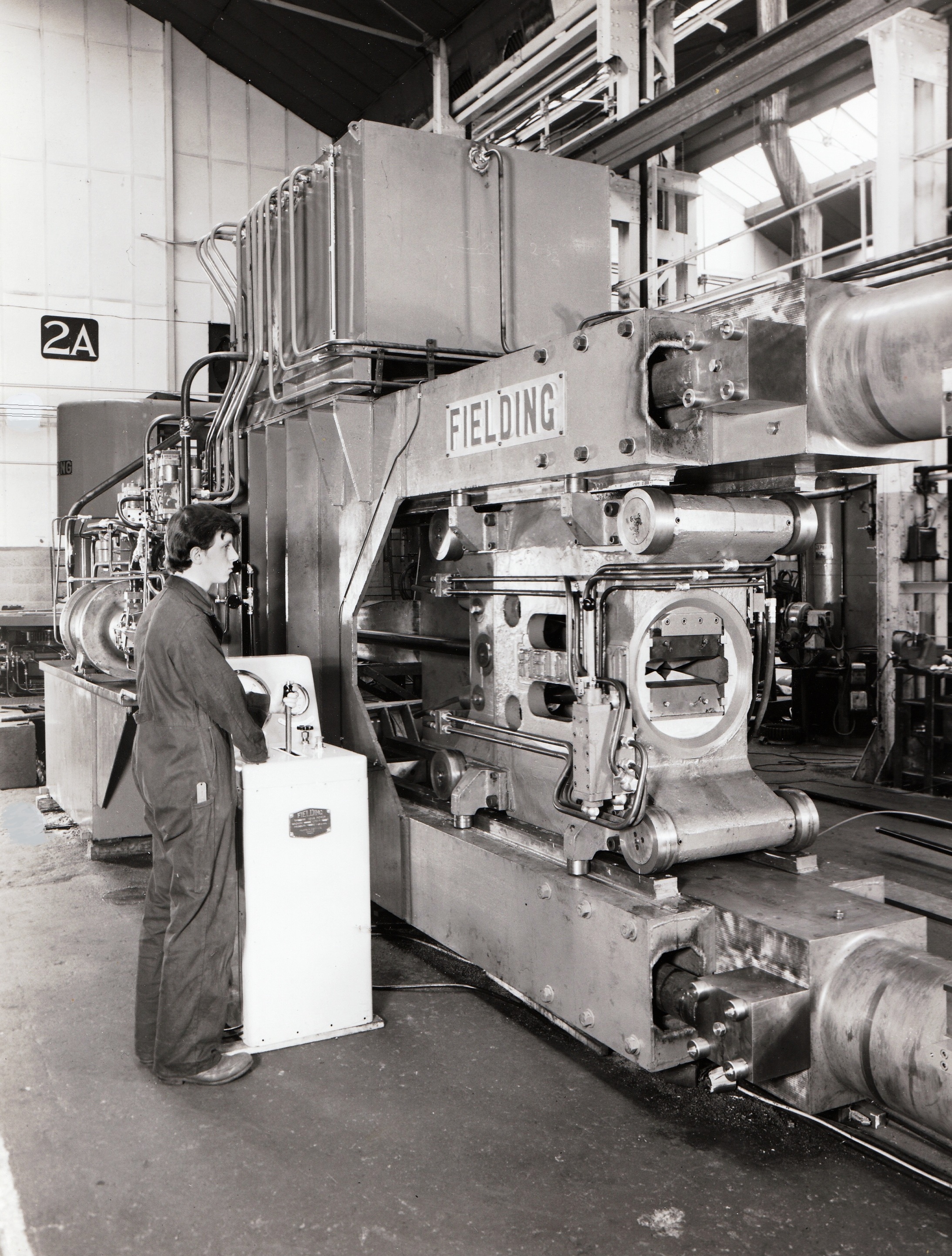
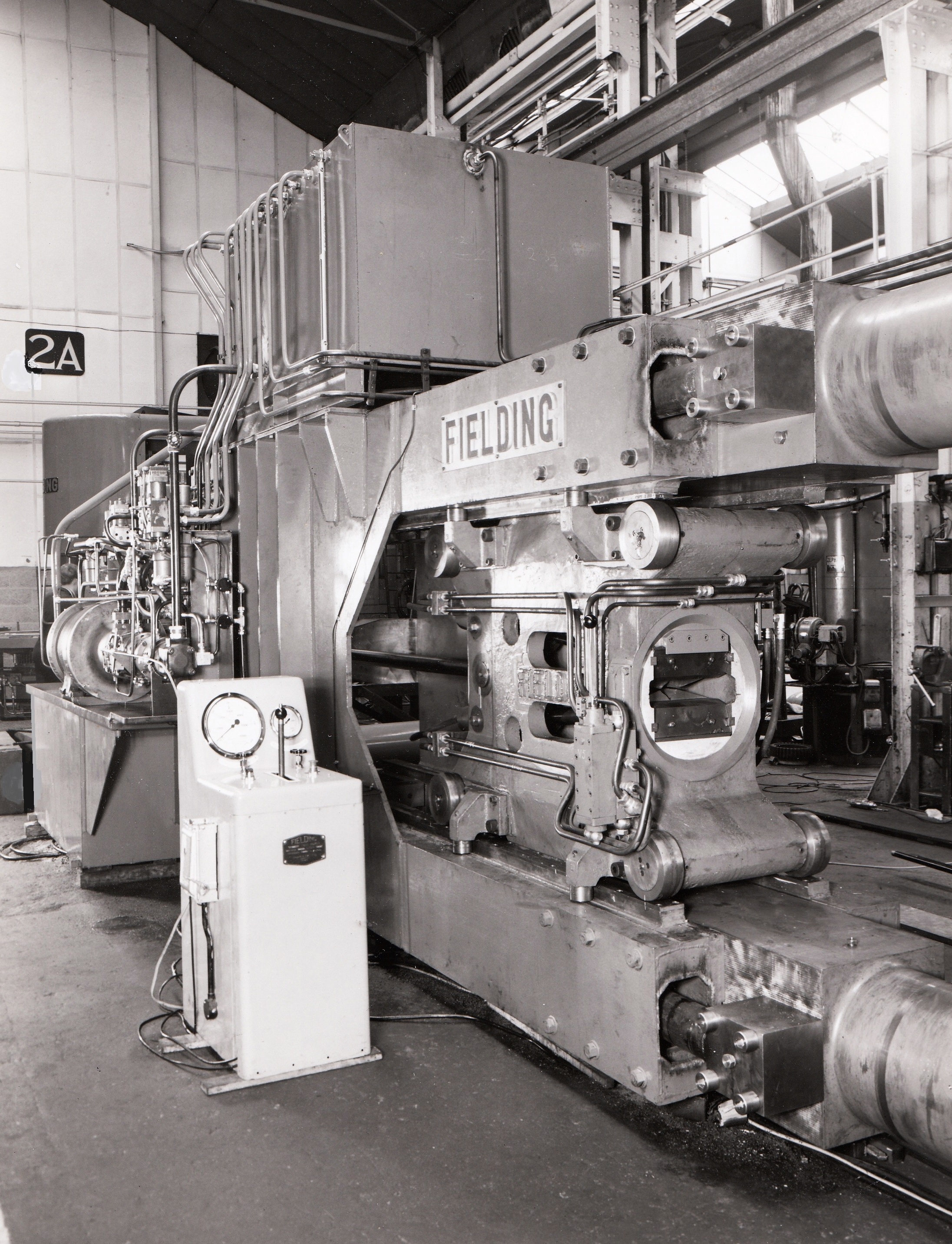
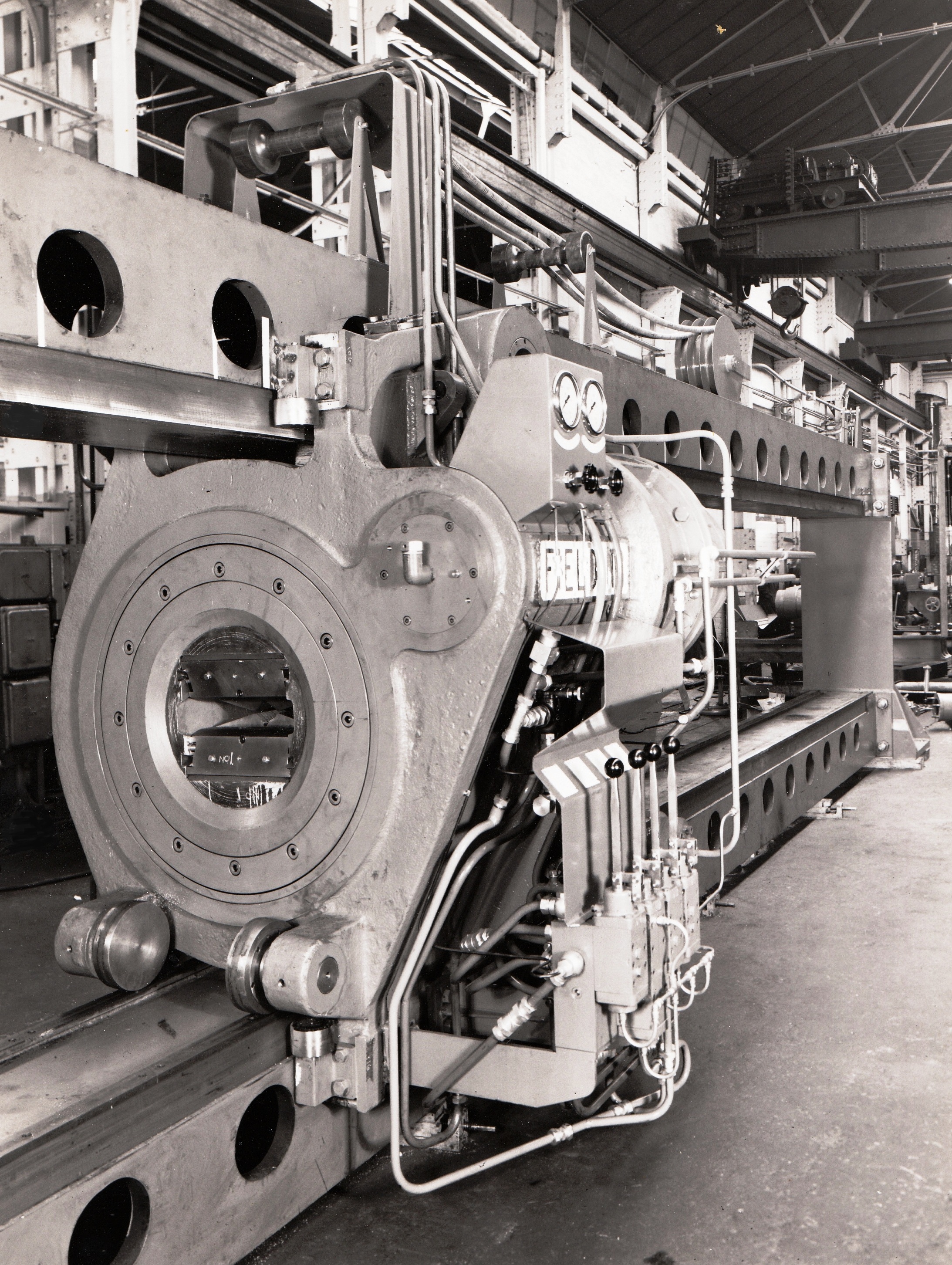
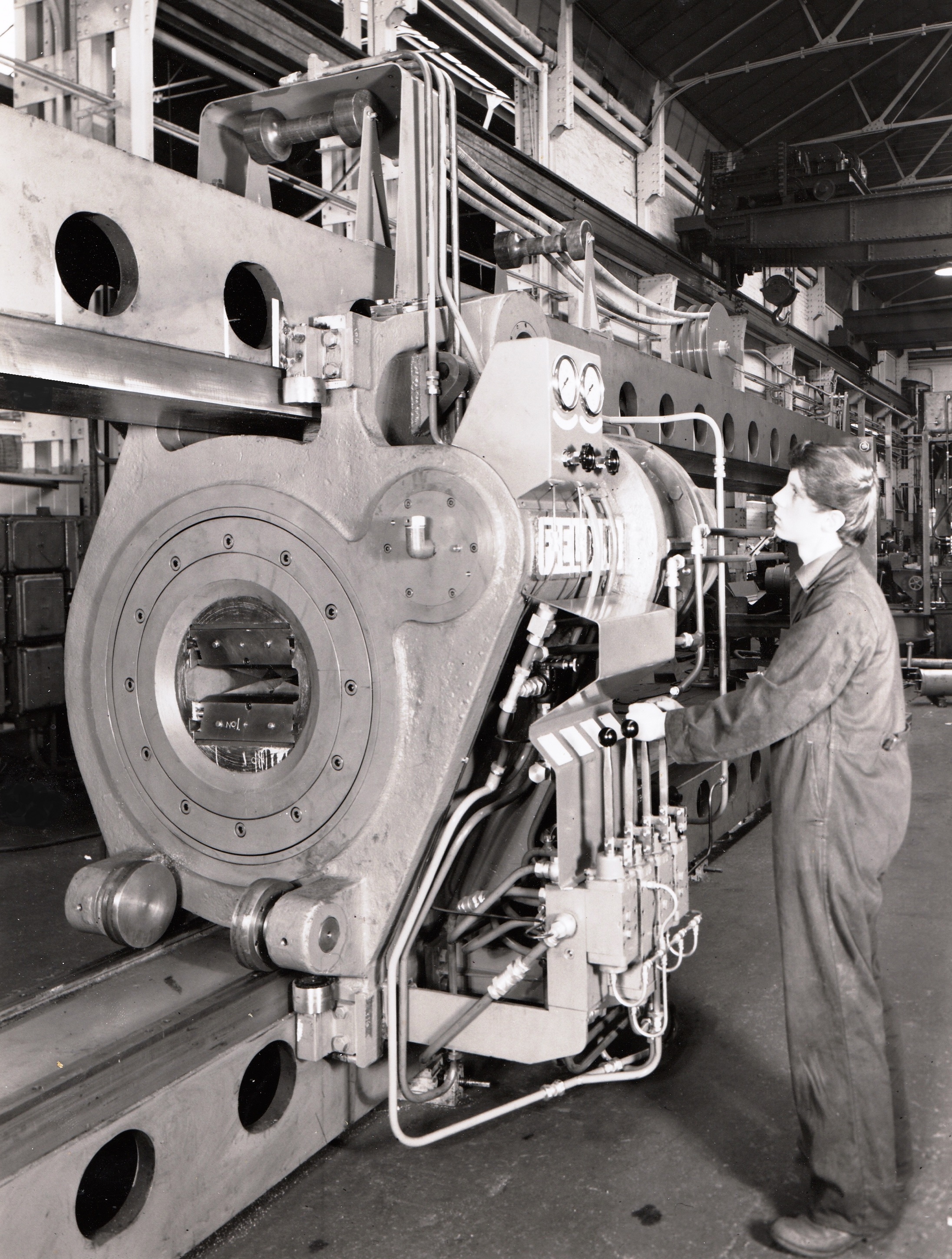
If you remember designing, machining, fitting, installing, maintaining, or working with this machine please share your memories at the bottom of the page by clicking on the words Add a comment about this page.


Comments about this page
Hi Chippy! Many thanks for posting your comments on the stretcher together with your detailed description of the method of operation. It should be of interest to others not so familiar with the workings of a section stretcher. Were you also involved in the installation and commissioning of the stretcher?
I can tell you that John, George and your good self will appear again in other photos in due course! John B
Hi John! In answer to your question about whether I was involved with the installation and commissioning, sadly I have to say that I wasn’t! That experience would have been great, but maybe I had to go back to college on block release at that time or something equally as dull! I can’t remember who installed the machine on site, but would hazard a guess that George Brown would have gone and maybe a pipe fitter and an electrician too. I think, but can’t be exactly sure, that one of the pipe fitters who worked on the job in the fitting shop was Sid Hatch, but as it was 46 years ago, details of some of the people who were involved in the build are hard to remember to say the least! I have just thought of something that did happen and was my fault was that we were going to lift off something to do with the oil tank, and I hadn’t noticed that I had put the sling under a fixed pipe as well as the piece we were going to lift! So you can imagine what happened next when either John or George took the load with the crane, the sling was so taught I you could have played a tune on it and then BANG it snapped !!! Not one of my most popular moves, but nothing got broken, me nor the machine, so I lived to fight another day so to speak! Chippy Aston
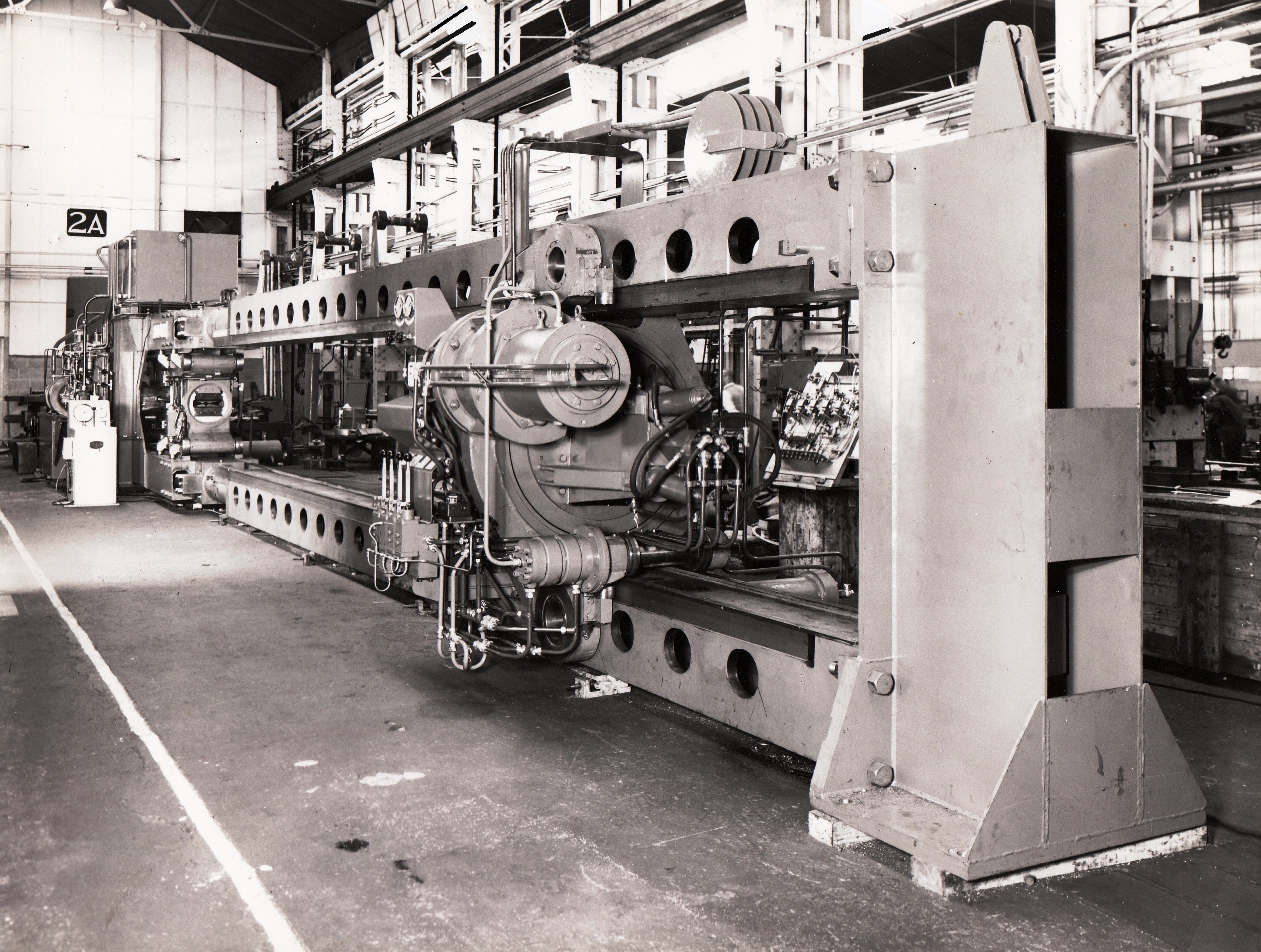
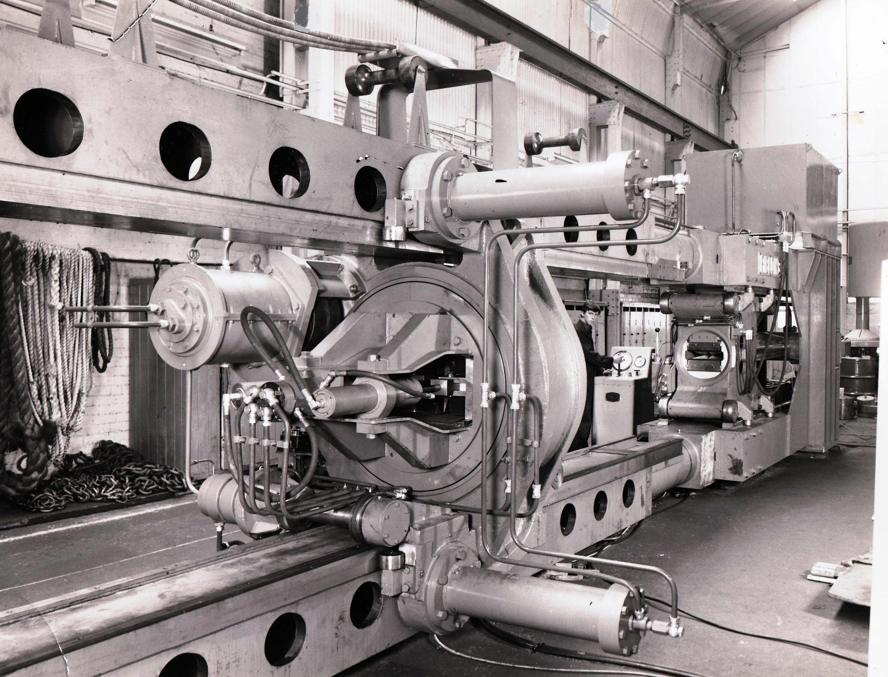
Hi John! I worked on this stretcher from start to finish, if I rightly remember, with John Mabbett and George Brown. I hadn’t been in Hyd 2 very long at the start of my ‘finalizing’ time as a fitter when I was put with John and George to assist them. They were both very good fitters and would make sure you understood what you had to do and to make a good job of it too! This involved driving the overhead cranes and doing a bit of ‘slinging’; I’d never done any of that before! Slings were the lengths of rope that we used for lifting things. I think they are now called, amongst other names, strops?
Some quite hefty lengths of copper came in from Enfield Rolling Mills for us to test the machine with, all fascinating stuff for a 17 year old ‘Chippy Aston’! It was the first time I had ever seen hydraulic motors and these were used to turn the de-twisting head and also for driving the de-twist head assembly along the bed of the machine. The de-twist head would be positioned in the appropriate place and two rams would be pushed through the holes you can see in the main frame. This would secure the de-twist head when the force was applied to the main rams at the other end which pulled the moving head backwards. The copper to be de-twisted and stretched would be clamped in the hydraulic jaws in the de-twist head and the moving head and the force applied to the moving head, taking it backwards, thereby stretching the copper and then de-twisting it with the other head, if required. The gripping jaws on both heads were angled so that even though the copper was gripped by them hydraulically, the angled jaws would grip the copper tighter and tighter as the force was applied.
I have a copy of photo’s No 1 and No 4, but I don’t remember getting get a copy of No 2 or No 3. Great to see a bit of my engineering history on the site. Thanks John!
Add a comment about this page