


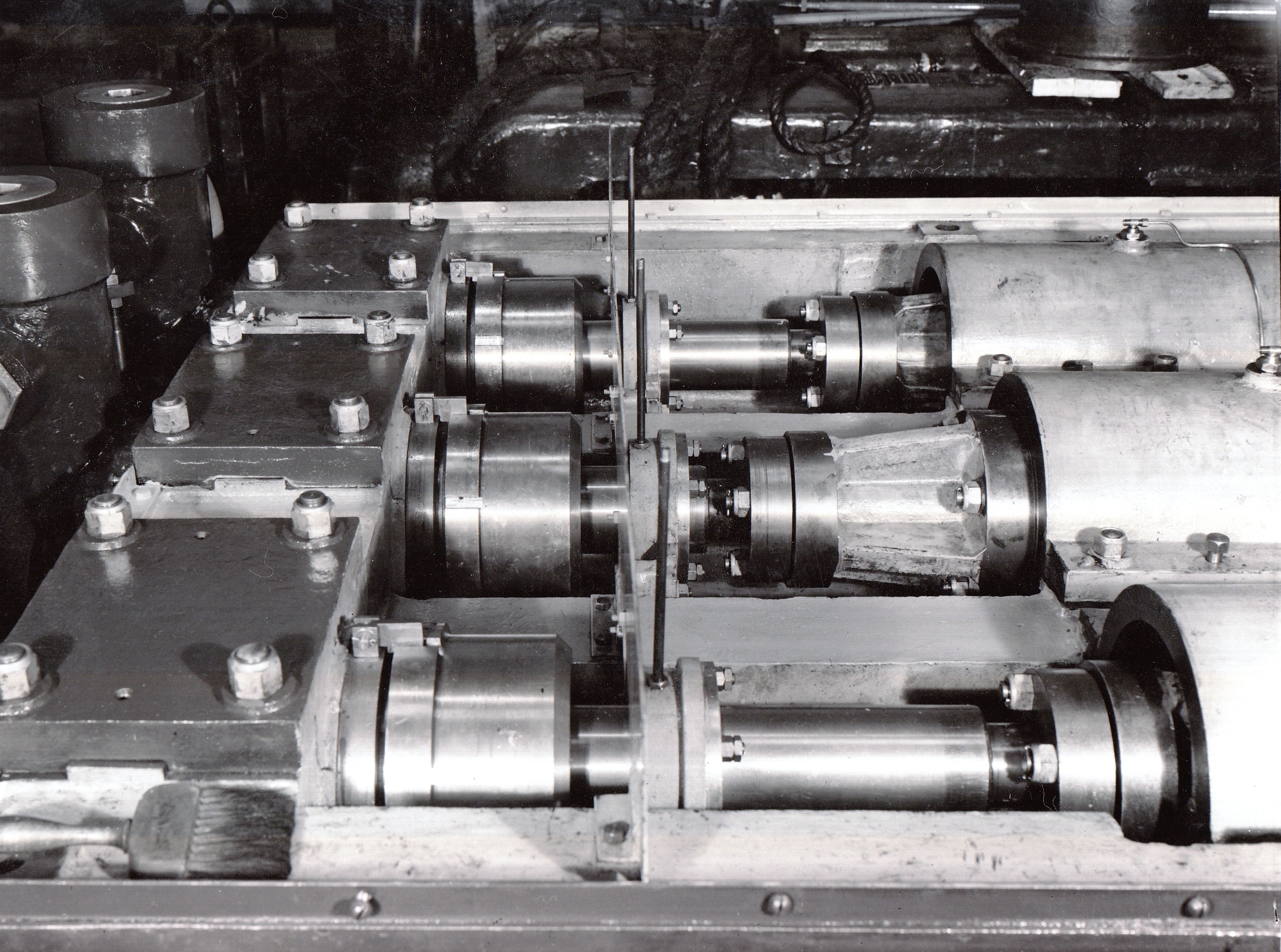
The second photo illustrates the partition plate and seal assembly separating the crankshaft end and the plungers and pump barrel end. (Separation being necessary when water is the pressure medium).
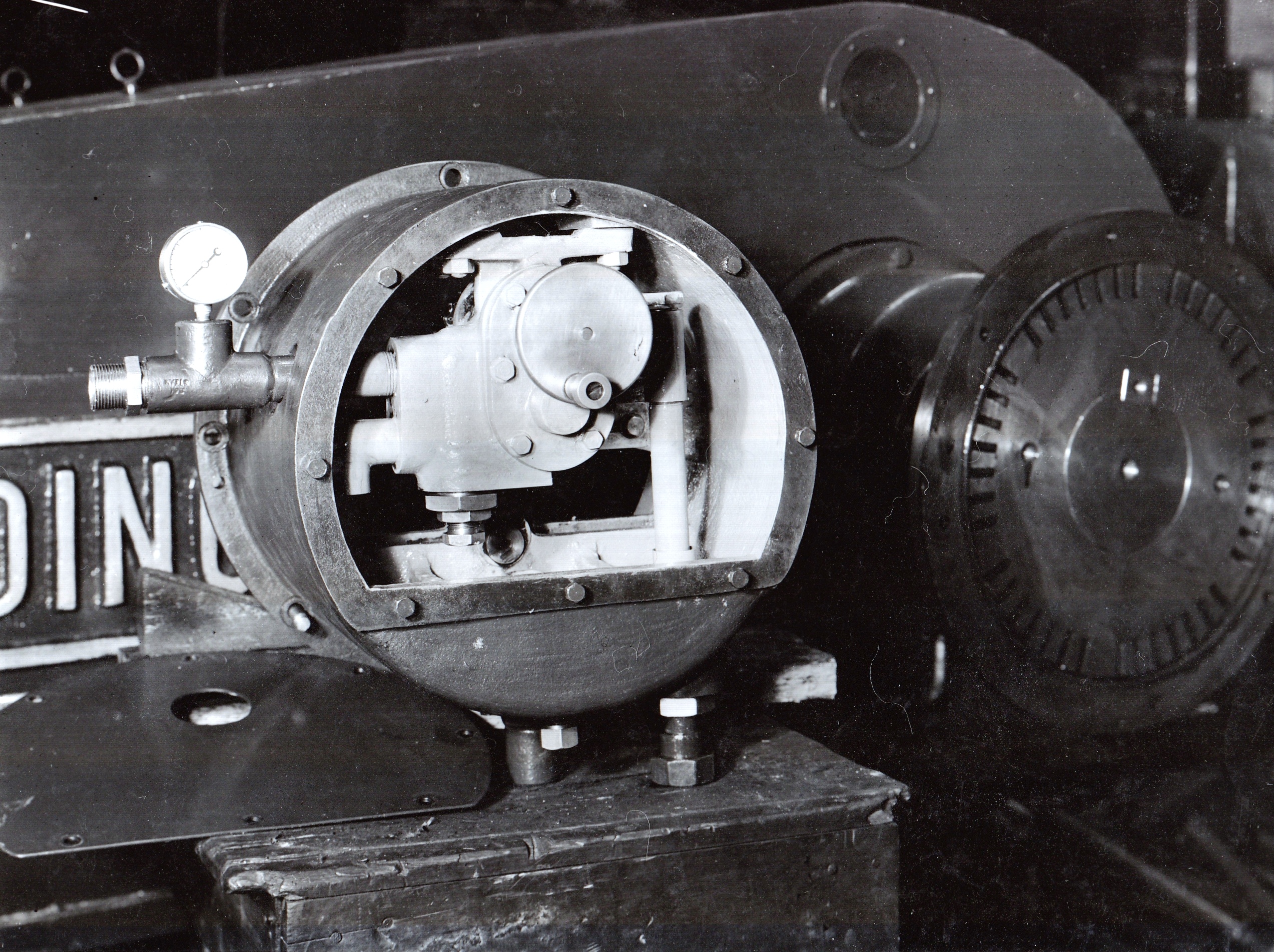
The third photo illustrates the mechanical lubricating pump (shown loose) that is attached to the non-driving side of the pump crankshaft.
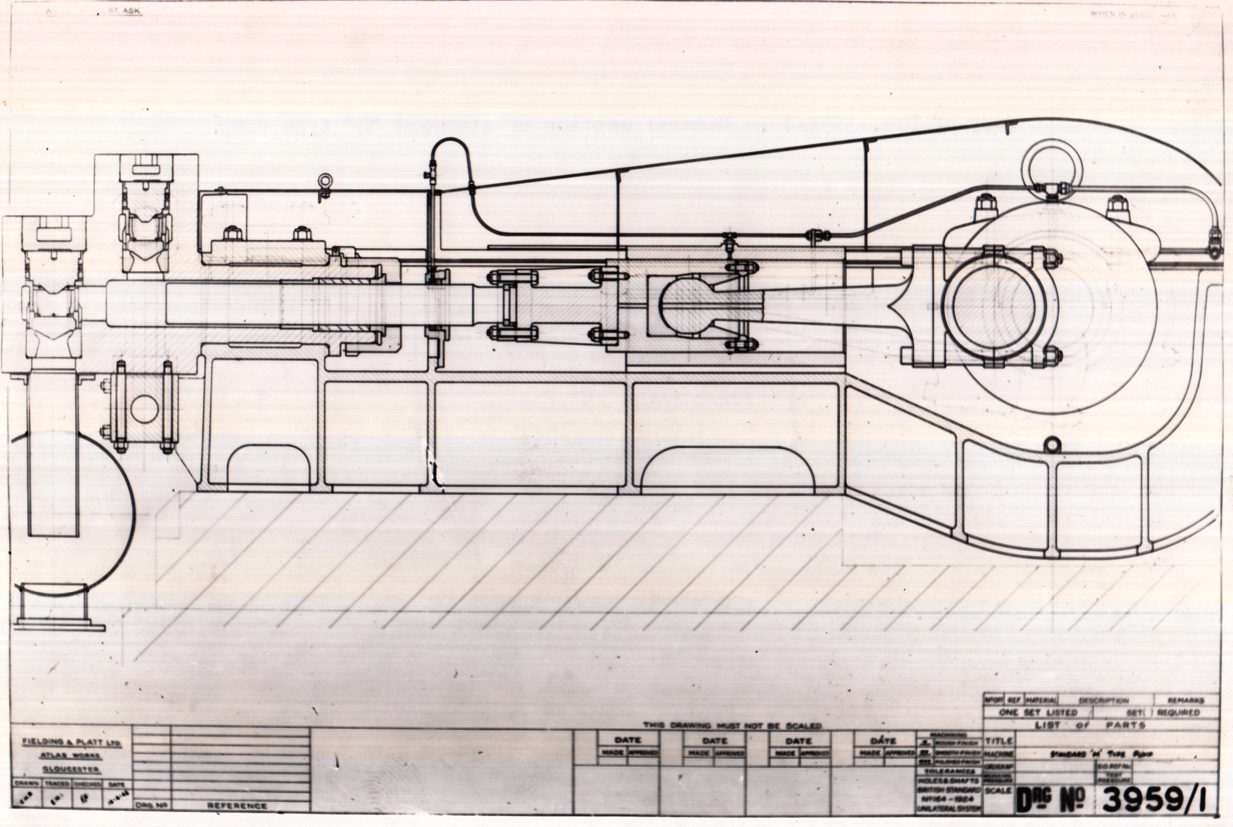
The fourth photo, taken slightly later in 1942 but applicable to most of the larger pumps of the era, illustrates a typical cross-section of the hydraulic pump
Click on a photograph to enlarge an image.
Click on the hyperlink to see Notable Orders from the 1940s.
If you have any recollections about working on larger pumps please share your memories at the bottom of the page by clicking on the words Add a comment about this page.


No Comments
Add a comment about this page